
Architectural drawings‚ often shared as PDF documents‚ visually communicate a building’s design; these include plans‚ elevations‚ and sections.
Plan drawings depict views from above‚ while elevation drawings show exterior facades‚ and section drawings reveal internal construction details.
PDF format ensures consistent viewing across platforms‚ making collaboration and archiving efficient for these crucial architectural plans.
What are Architectural Drawings?
Architectural drawings are the fundamental means of communicating a building or structure’s design‚ encompassing detailed visual representations used by architects‚ engineers‚ and construction professionals. These drawings aren’t merely artistic renderings; they are precise‚ technical documents conveying essential information about a project.

The core types include plan drawings – bird’s-eye views showing room layouts and spatial relationships; elevation drawings – orthographic projections displaying exterior facades; and section drawings – cut-through views revealing internal construction details like wall layers and structural components.
Increasingly‚ these drawings are distributed as PDF files due to their portability‚ scalability‚ and ability to maintain formatting across different devices and software. PDFs allow for easy sharing‚ viewing‚ and printing of complex designs‚ ensuring all stakeholders have access to the latest information. Properly organized PDFs are vital for project success.
The Importance of PDF Format for Sharing
PDF (Portable Document Format) has become the industry standard for sharing architectural drawings – including plan‚ elevation‚ and section views – due to its numerous advantages. Unlike native CAD files‚ PDFs ensure that the recipient views the drawing exactly as intended‚ regardless of their software or operating system.
This consistency is crucial for avoiding misinterpretations and errors during construction. PDFs also offer excellent compression capabilities‚ allowing for manageable file sizes even with large‚ detailed drawings. Security features within PDFs enable control over printing‚ editing‚ and copying‚ protecting intellectual property.
Furthermore‚ PDFs support layering and visibility controls‚ allowing users to selectively display or hide elements within the drawing. This facilitates focused review and collaboration. The widespread availability of free PDF readers makes it universally accessible‚ streamlining communication throughout the project lifecycle.
Understanding Plan Drawings
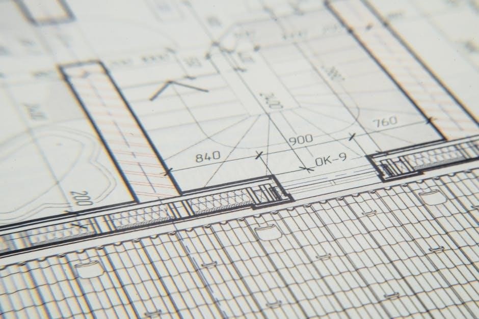
Plan drawings‚ often in PDF format‚ represent a horizontal cut through a building‚ showcasing room layouts‚ wall positions‚ and key architectural elements.
Scale and Dimensions in Plan Views
Plan views‚ frequently distributed as PDFs‚ rely heavily on accurate scaling and dimensioning to convey precise spatial information. Understanding the scale – for example‚ 1/4” = 1’ – is crucial for interpreting the drawing correctly; it dictates the proportional relationship between the drawing and the actual building.
Dimensions‚ indicated with numerical values and extension lines‚ specify the exact size and location of walls‚ openings‚ and other features. These dimensions are typically presented in feet and inches‚ or metric units‚ depending on the project’s standards.
Architects utilize various dimensioning techniques‚ including aligned‚ unidirectional‚ and chain dimensioning‚ to ensure clarity and avoid ambiguity. PDF viewers often include measurement tools allowing users to verify distances directly on the digital plan. Accurate scaling and dimensioning are fundamental for construction‚ fabrication‚ and overall project execution‚ making them vital components of any architectural PDF drawing set.
Symbols and Conventions Used in Plans
Architectural plans‚ commonly shared as PDF documents‚ employ a standardized set of symbols and conventions for efficient communication. Doors are typically represented by arc shapes indicating swing direction‚ while windows are shown as line patterns denoting glass and framing. Walls are differentiated by line weights – thicker lines for structural walls‚ thinner for partitions.
Symbols also denote fixtures like plumbing (toilets‚ sinks) and electrical outlets. Hatch patterns indicate material types‚ such as concrete or brick. North arrows orient the drawing‚ and scale bars provide a visual reference for dimensions.
Consistent application of these conventions is vital for clear interpretation by all stakeholders. PDF layering can enhance readability‚ allowing users to toggle the visibility of specific symbol sets. Familiarity with these symbols is essential for accurately reading and understanding architectural PDF drawings.
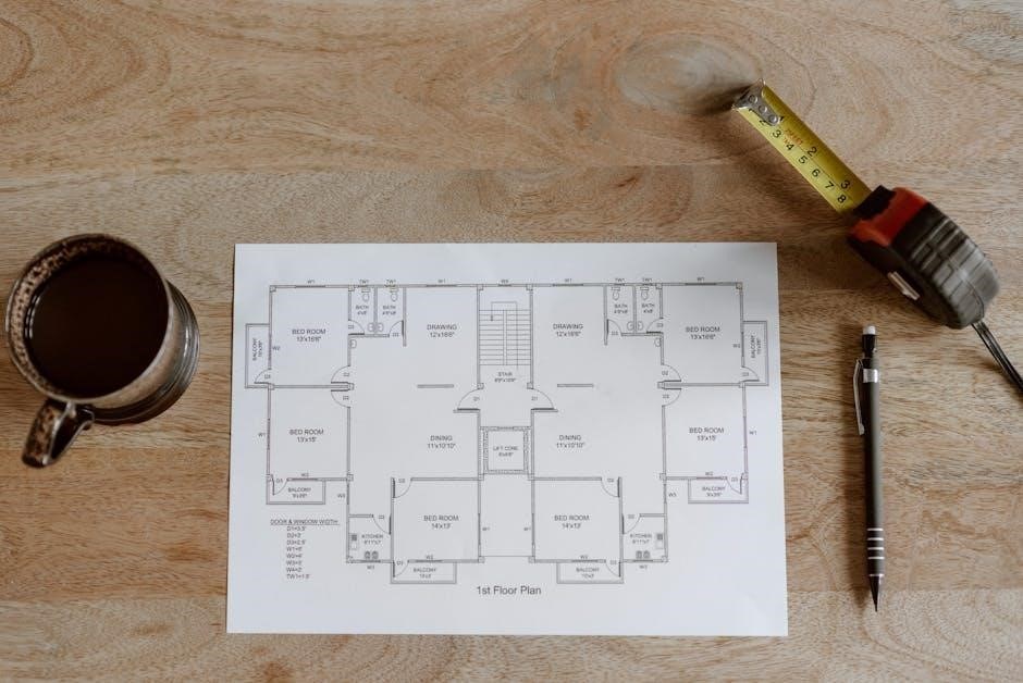
Reading Floor Plans: Walls‚ Doors‚ and Windows
Floor plans‚ frequently distributed as PDF files‚ are essential for understanding a building’s layout. Walls are depicted as lines‚ with thickness indicating material and structure. Exterior walls are generally thicker than interior partitions. Doors are shown with an arc representing the swing‚ crucial for space planning.
Windows are represented by line patterns‚ indicating glass and frame. Dimensions provide precise measurements for room sizes and wall lengths. Annotations clarify specific areas or features. Understanding these elements within a PDF allows for spatial comprehension.
Pay attention to wall labels indicating materials (e.g.‚ concrete‚ wood). Properly interpreting doors and windows is vital for furniture placement and circulation. PDF zoom functionality aids in detailed examination of these components‚ ensuring accurate interpretation of the architectural design.

Delving into Elevation Drawings
Elevation drawings‚ often in PDF format‚ showcase a building’s exterior views‚ detailing facade aesthetics and material finishes for clear visualization.
Exterior Elevations: Showing the Building’s Facade
Exterior elevations are orthographic projections representing the building’s facades as seen from different sides – typically north‚ south‚ east‚ and west.
These PDF-based drawings illustrate the building’s appearance‚ including exterior finishes‚ window and door placements‚ rooflines‚ and significant architectural features.
Architects utilize elevations to demonstrate the building’s aesthetic qualities and how it integrates with its surrounding environment.
Detailed annotations on the elevation drawings specify materials like brick‚ siding‚ or stucco‚ alongside dimensions and heights.
Properly scaled PDF elevations are crucial for contractors during construction‚ ensuring accurate material ordering and installation.
They also serve as vital communication tools for clients‚ providing a realistic preview of the finished project’s exterior appearance‚ often alongside rendered views.
Understanding elevation symbols and conventions is key to interpreting these essential architectural plans.
Interior Elevations: Detailing Internal Views
Interior elevations‚ often found within PDF architectural sets‚ provide detailed views of rooms as if looking directly at an interior wall.
Unlike floor plans‚ these drawings focus on vertical elements – showcasing cabinetry‚ built-in features‚ fireplaces‚ and wall treatments.
They are essential for illustrating specific interior design elements and ensuring accurate construction of custom features.
PDF format allows for clear presentation of material specifications‚ dimensions‚ and finishes directly on the elevation.
Contractors rely on interior elevations to understand the precise placement and detailing of interior components.
These drawings are particularly valuable for complex spaces or when unique design features are incorporated.
Interior elevations complement floor plans and sections‚ offering a comprehensive understanding of the building’s internal spaces‚ readily accessible in a digital PDF format.
Elevation Symbols and Material Representation
Elevation drawings‚ commonly distributed as PDF files‚ utilize standardized symbols to represent building materials and finishes efficiently.
Hatching patterns denote different materials like brick‚ siding‚ or stucco‚ while line weights indicate depth and prominence.
Symbols represent windows‚ doors‚ and other architectural features‚ ensuring clarity and consistency across the PDF documentation.
Material representation extends beyond patterns; color coding and texture indications can further clarify design intent within the PDF.
A comprehensive legend is crucial for interpreting these symbols and understanding the specified materials.
Accurate material representation is vital for cost estimation‚ construction detailing‚ and ensuring the final building matches the design.
PDF’s layering capabilities allow for toggling material visibility‚ aiding in focused review and analysis of the elevation details.

Exploring Section Drawings
Section drawings‚ often in PDF format‚ reveal a building’s internal structure by cutting through it; they illustrate wall construction and material layers.
What is a Section Cut?

A section cut is an imaginary plane that “slices” through a building‚ allowing architects to reveal the interior construction details in a drawing. Think of it like cutting a cake to see its layers – a section drawing displays what’s inside the building’s walls‚ floors‚ and roof.
These cuts are represented by a cutting plane line‚ typically indicated with hatching‚ on the plan drawing‚ showing where the “slice” was made. The resulting section drawing‚ frequently distributed as a PDF‚ provides a clear view of the relationships between different building elements.
This is crucial for understanding how walls are assembled‚ the height of floors‚ the structure of the roof‚ and the placement of foundations. Section drawings are essential for builders‚ engineers‚ and anyone needing to understand the building’s internal workings. They are vital for accurate construction and problem-solving‚ often included in comprehensive architectural plan sets.
Understanding Wall Construction in Sections
Section drawings are invaluable for deciphering wall construction‚ revealing layers of materials like insulation‚ framing‚ sheathing‚ and finishes. These details‚ often presented in PDF format for easy sharing‚ illustrate how walls are assembled to provide structural support‚ thermal performance‚ and fire resistance.
You can clearly see the different components – studs‚ plates‚ headers‚ and bracing – and their connections. The drawings also depict the wall’s relationship to the foundation and roof‚ showcasing how loads are transferred.
Understanding these details is critical for builders ensuring correct installation and for inspectors verifying code compliance. Detailed wall sections within architectural plans‚ readily available as PDF documents‚ minimize construction errors and ensure a building’s long-term durability and safety. They are a cornerstone of accurate building documentation.
Section Details: Foundations‚ Floors‚ and Roofs
Section drawings‚ frequently distributed as PDF files‚ provide critical insights into a building’s core structural elements: foundations‚ floors‚ and roofs. These detailed cuts reveal the composition of each‚ showcasing materials and construction techniques. Foundation sections illustrate footing depth‚ wall thickness‚ and drainage systems.
Floor sections depict joist direction‚ insulation layers‚ and subfloor materials‚ while roof sections reveal rafter or truss configurations‚ sheathing‚ and roofing materials. These architectural plans‚ often in PDF format‚ are essential for understanding how loads are distributed throughout the structure.
Detailed sections ensure proper construction‚ code compliance‚ and long-term building performance. They allow builders and inspectors to visualize the complete assembly‚ minimizing errors and maximizing structural integrity. Accessing these details via PDF streamlines communication and project management.

PDF Specifics for Architectural Drawings
PDFs are ideal for architectural plans‚ offering consistent viewing and compact file sizes; layering enhances visibility‚ while security features protect collaborative elevation and section drawings.
Optimizing PDF Size for Large Drawings
Large architectural drawings‚ encompassing detailed plan‚ elevation‚ and section views‚ often result in substantial PDF file sizes. This can hinder efficient sharing and storage. Several techniques can mitigate this issue. Firstly‚ utilize PDF optimization tools to compress images without significant quality loss. Reducing image resolution‚ particularly for less critical details‚ is effective.
Secondly‚ remove unnecessary elements like embedded fonts (if not crucial for editing) and unused layers. Vector graphics‚ inherent in CAD drawings‚ are generally more compact than raster images‚ so prioritize vector formats where possible. Consider creating PDF versions specifically for viewing versus printing; the viewing version can be more aggressively compressed.
Finally‚ explore tiling options‚ breaking large drawings into smaller PDF segments. This improves accessibility and reduces individual file sizes‚ facilitating easier distribution of complex architectural plans.
Layering and Visibility in PDF Architectural Plans
PDFs created from plan‚ elevation‚ and section drawings often retain the layer structure from the original CAD software. This is incredibly valuable for controlling visibility and extracting specific information. Layers allow users to toggle the display of different building components – for example‚ showing only structural elements or concealing furniture.
This functionality streamlines review processes‚ enabling consultants to focus on their areas of expertise. Utilizing PDF viewers with layer support is crucial to access these features. Properly organized layers‚ with descriptive names‚ enhance usability.
Furthermore‚ PDF layering facilitates creating customized views for presentations or construction documentation. Selective visibility ensures clarity and prevents information overload‚ making complex architectural plans more accessible and manageable for all stakeholders.
PDF Security and Permissions for Collaboration
Sharing plan‚ elevation‚ and section drawings as PDFs necessitates careful consideration of security and collaboration controls. PDFs allow for password protection‚ restricting access to authorized personnel only. Permissions can be customized‚ enabling viewing‚ printing‚ or editing rights on a user-by-user basis.
This granular control is vital for protecting intellectual property and maintaining design integrity. Digital signatures can authenticate the document’s origin and ensure it hasn’t been tampered with. When collaborating with external consultants‚ setting appropriate permissions prevents unintended modifications.

Utilizing PDF features like redaction allows for the removal of sensitive information before sharing. Secure PDF workflows streamline the review process while safeguarding valuable architectural plans and maintaining project control.
Resources for Finding Plan‚ Elevation‚ and Section Drawings (PDF)
Online databases and government websites offer accessible architectural plans in PDF format‚ providing valuable resources for designers and researchers alike.
Online Architectural Plan Databases
Numerous online platforms specialize in hosting architectural drawings‚ frequently available as downloadable PDF files. These databases cater to a wide range of needs‚ from homeowners seeking inspiration to professionals requiring detailed construction documents.
Websites like ForumConstruire.com provide extensive collections of house plans‚ often categorized by style‚ size‚ and features. These resources frequently offer both free and premium plans‚ with varying levels of detail and customization options. Searching these databases allows users to filter results based on specific criteria‚ streamlining the process of finding relevant plans‚ elevations‚ and sections.
Other platforms aggregate plans from various architects and designers‚ creating a centralized repository of architectural PDFs. These sites often include advanced search functionalities and tools for comparing different designs. Remember to always verify the source and licensing terms before using any downloaded PDF for construction or professional purposes.
Government and Municipal Building Plans (PDF Access)
Many local and national governments offer public access to building plans‚ often in PDF format‚ representing a valuable resource for researchers‚ developers‚ and those interested in historical architecture. These records typically include detailed plans‚ elevations‚ and sections submitted during the permitting process.
Accessing these documents often requires navigating municipal websites or utilizing online portals dedicated to public records. Search functionalities allow users to locate plans based on address‚ permit number‚ or other relevant identifiers. The availability of PDF versions simplifies viewing and archiving these large-format drawings.
However‚ it’s crucial to note that access policies and the level of detail available can vary significantly between jurisdictions. Some municipalities may redact sensitive information before making plans publicly available. Always respect copyright and usage restrictions when utilizing these architectural PDFs.